|
|
 |
| |
 |
| |
 |
| |
|
SGE DOUBLE LINE USING UFSBI |
| |
|
|
The Universal Fail Safe Block Interface Equipment UBX -2000 is meant for interfacing various signaling
information of a block instrument at one end of a block section and exchanging them with the block
interface equipment at the other end through a digital transmission equipment (optical or radio) ensuring
high degree of safety and availability. |
| |
|
|
|
Safety of a block instrument is ensured by a foolproof logic sequence and relay interlocking. Safety for
the Block Interface Equipment means it must correctly acquire the signal and reproduce it at the other end
without any error. In case of any failure, it is detected and the system is lead to a fail -safe state. |
| |
|
However, there are some very remote possibilities when t he system may not be able to detect a failure
which may lead to an unsafe situation. This is defined as Mean Time between Wrong side Failure
(MTBWSF) and according to RDSO specification SPN 147/2005, the figure is 10 9 hrs. This can be very
well ensured by using 2 out of 3 hardware redundancy logic at the I/O Interface and processor level. With
2/3 redundancy system, as soon as an anomaly is detected, the system is forced to a fail -safe state leading
to a RED signal. Mishaps are thus avoided, but the mov ement of the train is also restricted. To increase
the availability of the system, thus triple hardware redundancy has been proposed at the I/O interface and
Processor level so that even if a failure is detected in one set of hardware fail safe operation can still
continue with 2 sets of hardware, thereby increasing availability. Better availability is also ensured by
using dual redundant power supply unit for the system. |
| |
|
-
Designed for fail safe operation.
-
Triple redundant hardware at all levels with 2/3 decision logic ensures high degree of safety as well as
availability.
-
System meets CENELEC & ORE 155 guidelines for safety and reliability.
-
System meets RDSO specification SPN-144 and SPN-147/2005 for all types of Block Instruments in
operation in Indian Railways.
-
Simple, modular and rugged design.
-
High performance 16 bit Intel 80C196KC Microcontroller
used for better software management.
-
CMOS/FET active components to ensure low power consumption and better reliability.
-
Hi-rel components, relays and connectors used to ensure high MTBF.
-
All input-output connections are optically and/or galvanically isolated to eliminate ground noise and
earth faults.
-
Rugged communication protocol for transmission of error-free data.
-
Dual power supply in hot-standby mode increases system availability.
-
16-digit dot-matrix alpha-numeric display for user friendly man -machine interface.
-
Environment specification meets IS-9000.
|
|
| Safety and Availability are the two keywords which are reflected in all the stages of the system design. |
| |
|
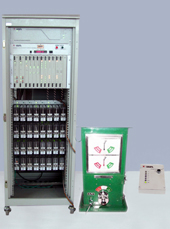
The system is housed in a 19 inch subrack, 6U (10.5 inches) high, which is fixed inside a closed rack of
approx 5 ft high. The front panel of the closed rack is a hinged door fitted with transparent plastic sheet
so as to enable the operator to see the LEDs and displays of the system. The door is also provided with a
lock to protect the system from unauthorized access. The rear panel of the closed rack is normally fixed
with screws. The various cards which have been used in the system are as follows: |
 |
Power Supply Unit |
|
System Module |
|
Communication Driver Unit |
|
Relay Input Interface Module |
|
Relay Output Module |
|
Relay Feedback Module |
|
Display and Reset Panel |
|
Alarm Extender Module |
|
Alarm Panel For SM |
|
|
|
|
The above modules are housed in a passive backplane which has the provision of accommodating 12
modules. The basic system consists of two power supply units connected back to back, three system units
and one communication driver unit. The above modules consume six fixed slots. The subsequent six
slots are for accommodating two nos. of each of Input, Feedback and Output modules. The last slot is not
used. |
| |
| The position of the power supply unit, the system unit and the communication driv e unit is fixed on the
backplane. To avoid insertion of wrong card in a slot, the connectors have relative offset so that only the
right card will be accepted in the right slot. Input, Output and Feedback module have fixed position on
the backplane. |
| |
| The backplane accepts two input modules in slot 7 & 8, two feedback modules in slot 9 & 10 and two
output modules in slot 11 & 12. Input signals received through slot 7 will be output through slot 11 at the
other end of the UFSBI system. Feedback of output signal of slot 11 is taken through the feedback
module of slot 9. Thus the three cards of slot 7, 9 & 11 forms a composite set of first 8 input / output.
Similarly the three cards of slot 8, 10 & 12 forms a composite set of rest 8 input / output. |
| |
| The each of the I/O Modules has triple redundant hardware for the same external I/O signal to ensure the
safety and availability of the system. These I/O modules are interfaced to the three processors through
three separate universal I/O bus. The degree of saf ety specified is ensured not only by hardware but also
by software taking inputs and feedbacks from various stages of the system. |
| |
| All the alarms and status of the system are displayed with various onboard LEDs on each of the modules.
Further a 16 character alphanumeric display panel/module is used to prompt the various alarm conditions
with short mnemonics for easy understanding of the problem. The display panel is fitted at the top of the
subrack and is common for all the three processors. In case of a larm in the system a piezo buzzer is
activated to draw the attention of the operating staff. Acknowledgement of alarm through a key on the
display panel stops the buzzer but the alarm is still displayed on -line as long as it is continued. The
display panel also accommodates external resetting provision and the veeder counter for registering these
resets. |
| |
| The Alarm Extender Module provides alarm indications to the SM�s Panel and relay contacts for external
data logger for logging various alarm conditions . It also performs the optional signal amplification for
combating cable losses ( upto 30dB ) when two UFSBIs are connected through QUAD cables. |
| |
| The Q-series relays for interfacing various I/O signals are fitted in a panel at the bottom of the closed
rack. Wiring of the various external relays of the Block Instrument for interlocking are done through the
front and back contacts of the Q-series safety relay inside the rack. |
|
|
|
This equipment is capable of driving safety signaling relays conforming to specification BRS:930 (QSeries). |
|
The equipment is capable of working on Telecom Cable as well as Voice Channel provided over
Optical Fibre or Microwave systems. |
|
This interface equipment conforms to the voltage and current requirements , impedance matching and
other electrical characteristics of the block instrument (SGE type). |
|
The coding of signal transmission takes care of types of noise generally encountered in the
transmission system and ensure safety of operation against these noise . |
|
Each interface equipment in the section has a unique address which is settable through backplane
jumpers. |
|
The information exchanged between the pair of the interface equipment contains the source &
destination address. |
|
Wrongly addressed information pac kets are promptly rejected by the system. |
|
The bell of the Block Instrument shall work on E/M signaling of Voice Channel. Alternatively, the
bell may be worked through this. |
|
The block telephone will work on a separate voice channel. |
|
The system works on 24V (+20% to -10%). |
|
The resetting facility has been provided in the Display and Reset Panel to bring back the UFSBI into
normal operation which has gone into shutdown state. The procedure for resetting has been provided
in the functional description of Dis play and Reset Panel under the heading �Procedure � Reset
Operation�. |
|
|
| TECHNICAL SPECIFICATION |
|
| SYSTEM SPECIFICATION |
|
Meets RDSO SPN 147/2005 |
| SYSTEM CONFIGURATION |
|
Triple redundancy at all levels including
processor |
| CENTRAL PROCESSOR |
|
Hight Performance 16 bit Intel 80C 196KC Microcontroller |
| SAFETY COMPLIANCE |
|
| Hardware |
: |
CENELEC EN 50129 |
| |
|
ORE 155.A |
| |
|
RSDO SPN 144 & SPN 147
/ 2005 |
| Software |
: |
CENELEC EN 50128 |
|
| I/O MODULES |
|
|
| Input Module |
|
16 change over input, Opto isolated with
transient suppressor |
| Output Module |
|
16Q series Relay output with 8F / 8B contacts |
| |
|
Transient protected |
| |
|
Short circuit protected |
| Note:
Output module needs an Input module for getting feedback from the external signaling
relay driven by the system. |
| |
| COMMUNICATION |
| FSK, V.23 |
|
1200 Baud |
| 1302/2097Hz |
|
|
| 4QAM V.22.bis |
|
2400 Baud (not used) |
| Send level |
|
-8 dBm nominal |
| Receive Level |
|
-12 dBm nominal |
| S/N Ratio |
|
better than 20dB for BER 10-6 |
| |
| POWER
SUPPLY |
| Configuration |
|
Hot-standby |
| Input |
|
24 V DC nominal |
| |
|
21.6 V DC to 28.8 V DC |
| Output |
|
+5.8 V Dc, +- 0.3 V, 1.5 AMPS (Int) |
| |
|
+12.8 V Dc, +- 0.5 V, 4 AMPS (Int) |
| Consumption |
|
20 Watts (nominal) for basic system
(excluding the activation drive of external signaling relays) |
| Protection |
|
Input : Surge and transients, Overvoltage alarm, Over voltage shutdown, Undervoltage alarm, Undervoltage shutdown |
| |
|
Output: Overvoltage and short-circuit |
| Efficiency |
|
>70% at optimum load |
| ENVIORNMENT |
|
QM333 Catagory B2 |
| Temparature |
|
As per RDSO/SPN/147/2005 |
| Humidity |
|
As per RDSO/SPN/147/2005 |
|
MECHANICAL |
|
Sub-rack of UBX 2000 is 19" wide,
6U high
Closed Rack (standard) is 600mm wide, 32U high |
| |
| Downloads |
|
|
|
Video |
| |
| |
|
BACK TO FAIL SAFE MULTIPLEXER |
|


